Table of Contents
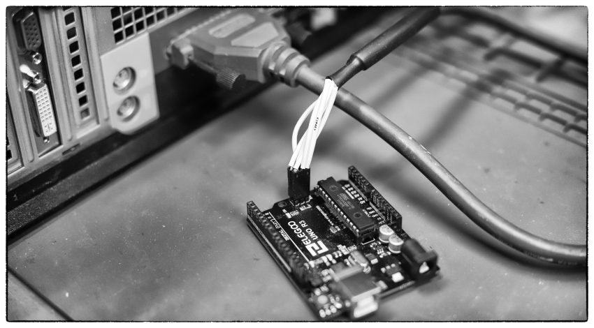
It is possible to burn an Arduino bootloader with nothing more than a computer and parallel port cable. Finding a system with a parallel port is the hard part. Anything newer than a Core 2 Duo will be hit or miss for legacy ports — so a pre-2010 computer is a good place to start.
A word on resistors. I’ve seen this done before and it’s recommended that you use some kind of resistor on the MOSI, MISO, and SCK lines. I managed to do this without resistors. So if you don’t have any resistors, plain jumper wires will work in a pinch.
Making a cable
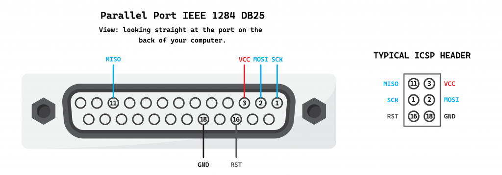
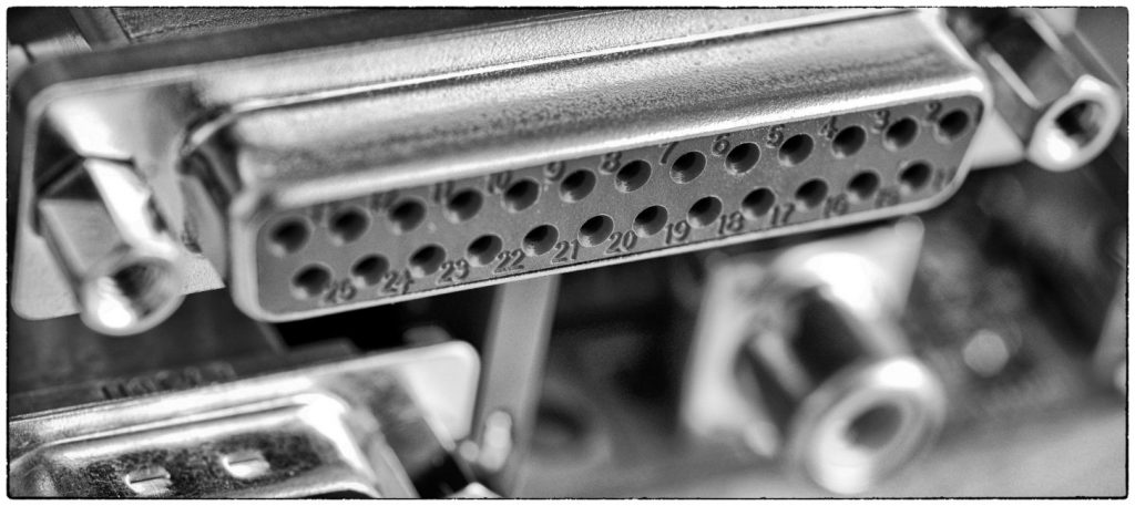
Parallel port pinout
You have two options here. Find a parallel port cable and cut the end off, or stick jumper wires directly into the holes of your parallel port. I’ve done it both ways. Either one works, but modifying an old printer cable makes for a more reliable connection.
Pins defined in software
These pins are defined by avrdude in “/etc/avrdude.conf”. We’ll look at avrdude later, but this is how the pins are mapped by default.
programmer
  id = "dapa";
  desc = "Direct AVR Parallel Access cable";
  type = "par";
  connection_type = parallel;
  vcc   = 3;
  reset = 16;
  sck = 1;
  mosi = 2;
  miso = 11;
;
You can change this mapping to suit your needs. Just be aware that not all parallel port pins are the same. Some are only ground lines, some are data lines, etc. You can mix and match data lines, but you can’t use a gound line as a data line.
My custom cable
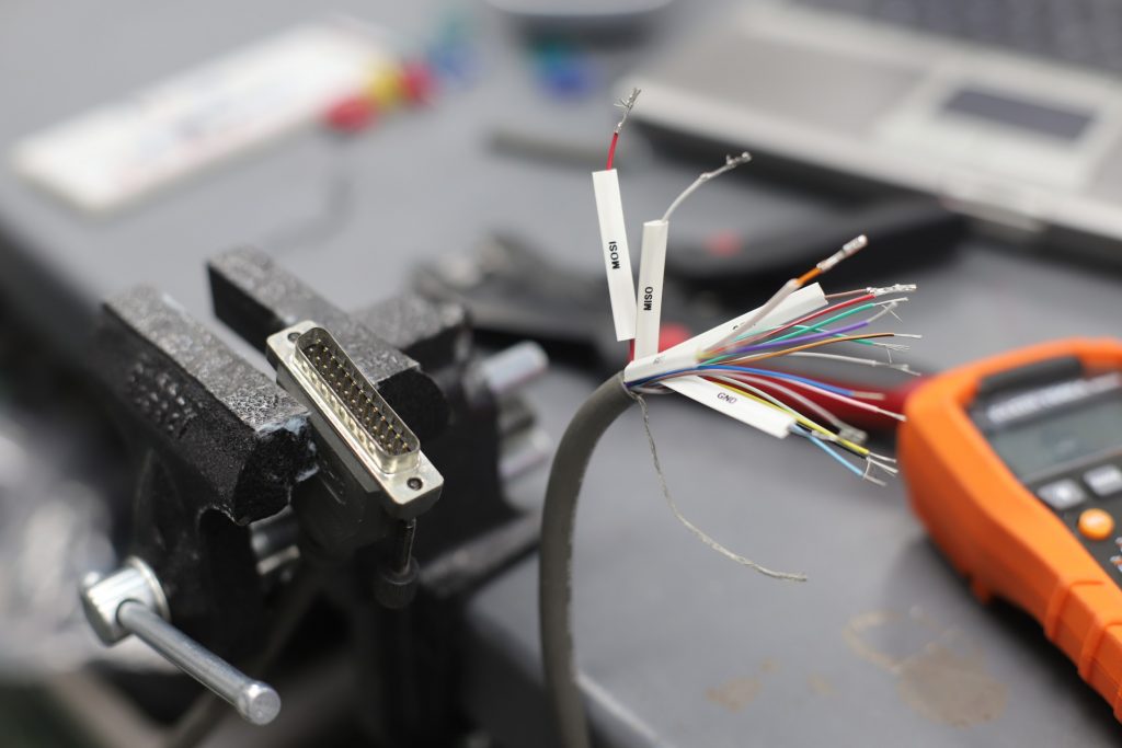
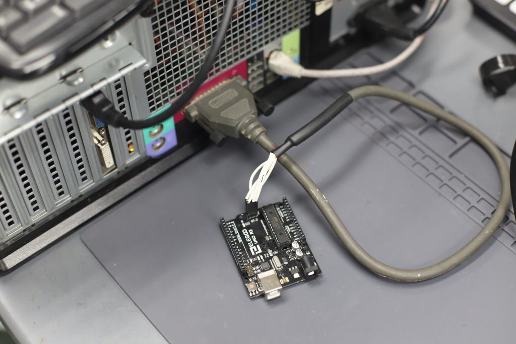
If you cut a cable, you’ll need a multimeter to determine which wires go to the pins you need. I ended up using heatshrink labels on mine and crimping the ends with a Dupont connector.
Some parallel port cables have two wires per pin, others just one.
Connecting the cable
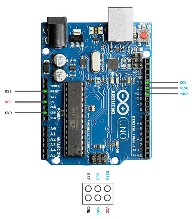
However you make your cable, you will need to connect it to the ICSP pins of your target device. Here I have an Arduino Uno with the ATmega328 microcontroller. I connect my cable directly to the ICSP headers. If you’re using male “jumper cables”, then your best bet is to connect it to the female connectors on the perimeter of your Arduino board.

Installing software
This will all be done through Linux. I tried this in Windows, but didn’t have any luck. I got it to work in Windows once or twice, but the results were intermittent — the Arduino IDE seemed to write correctly, but the read/verify would fail.
screen
screen is used as the serial port monitor (to see serial port messages)
apt-get install screen
curl
apt-get install curl
arduino-cli
The ‘arduino-cli’ package is used to compile your sketch and bootloader.
After running the install script, the arduino-cli binary installs to the ‘current directory’ — you can either invoke it from that directory or move the binary to /usr/local/bin
# Download arduino-cli install script and execute
curl -fsSL https://raw.githubusercontent.com/arduino/arduino-cli/master/install.sh | sh
# arduino-cli useful commands
# install boards
arduino-cli core update-index
arduino-cli core install arduino:avr

# get boards list
arduino-cli board listall

# add board manager url
arduino-cli config add board_manager.additional_urls https://raw.githubusercontent.com/damellis/attiny/ide-1.6.x-boards-manager/package_damellis_attiny_index.json
# search core
arduino-cli core search attiny
# install
arduino-cli core install attiny:avr

# library list
arduino-cli lib list
# search for library
arduino-cli lib search “stepper”
# install library
arduino-cli lib install "AccelStepper"
avrdude
‘avrdude’ is what will be used to upload the bootloader through the parallel port.
apt-get install avrdude

Compiling and uploading sketch
Just like with the Arduino IDE, the sketch you create will need to be inside a directory with the sketch name. So your “Blink” sketch will be a file called blink.ino inside of a directory called blink.
Compile sketch
arduino-cli compile --fqbn arduino:avr:uno -v blink/ --output-dir blink
Upload using avrdude
This is where you plug in your parallel port cable to the Arduino. The parallel port device should be ‘/dev/parport0’
avrdude -p atmega328p \
-c dapa \
-P /dev/parport0 \
-U flash:w:"blink/blink.ino.with_bootloader.hex":i \
-U lfuse:w:0xf7:m \
-U hfuse:w:0xd6:m
Once the bootloader is uploaded, you should be able to upload sketches the “normal” way with the Arduino IDE. You can also use ‘arduino-cli’ to upload sketches. Here, my USB serial port is ‘/dev/ttyACM0’
arduino-cli upload -v --port /dev/ttyACM0 --fqbn arduino:avr:uno blink/
Serial monitor
The ‘screen’ program can be used to get output from the serial monitor through a USB cable. This is not meant to be used with the parallel port cable.
screen /dev/ttyACM0 9600

